QS 10 kw Hub Motor Wiring Diagram PDF: A Comprehensive Guide
In the realm of electric vehicle technology, the QS 10 kw Hub Motor has been gaining significant attention. A crucial aspect of understanding and working with this motor is its wiring diagram, which is now available in a PDF format.
The Significance of the Wiring Diagram
The QS 10 kw Hub Motor Wiring Diagram PDF serves as an essential technical document for various stakeholders. For engineers, it is a blueprint that guides the design and integration of the motor into electric vehicle systems. Technicians rely on this diagram for proper installation and maintenance of the hub motor.
Detailed Breakdown of the Diagram

qs 10 kw hub motor wiring diagram pdf
Motor Cables
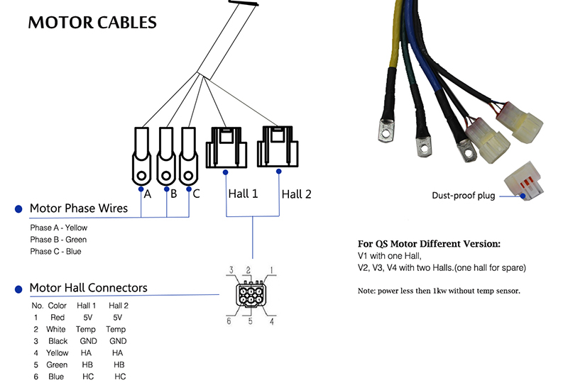
The diagram prominently features the motor cables section. It clearly identifies two main categories: Motor Phase Wires and Motor Hall Connectors.
Motor Phase Wires
- Phase A: Represented by a yellow wire.
- Phase B: Identified with a green wire.
- Phase C: Marked by a blue wire.
These phase wires are connected to terminals labeled A, B, and C, respectively.
Motor Hall Connectors
The color – coding for the Motor Hall Connectors is as follows:
- Red Wire: Supplies a 5V power source to both Hall 1 and Hall 2.
- White Wire: Connects to the temperature sensor (Temp) for both Hall sensors.
- Black Wire: Serves as the ground (GND) connection for both Hall 1 and Hall 2.
- Yellow Wire: Connects to Hall sensor A (HA) for both Hall sensors.
- Green Wire: Links to Hall sensor B (HB) for both Hall sensors.
- Blue Wire: Connects to Hall sensor C (HC) for both Hall sensors.
Additional Notes
The diagram also includes important notes. For QS Motor different versions (V1, V2, V3, V4 with two Halls, one hall for spare), it mentions that the power is less than 1kw without a temp sensor.
Implications for the Industry
The release of the QS 10 kw Hub Motor Wiring Diagram PDF has far – reaching implications. It promotes standardization in the installation and maintenance of these hub motors. Manufacturers can ensure the quality and reliability of their electric vehicles by adhering to the wiring specifications provided in the diagram.
In conclusion, the QS 10 kw Hub Motor Wiring Diagram PDF is a valuable resource that enhances the understanding and application of this powerful hub motor in the electric vehicle industry. It is a tool that will contribute to the continued growth and innovation in the field of electric transportation.
